Propgation
Direction: The general plane wave solution to the wave equation may travel in an arbitrary direction. The propagation direction of this arbitrary plane wave is represented by the propagation vector k. Note that k is normal to the wavefronts (planes of constant phase) and that k has a magnitude 2pn/l = wn/c in a nonmagentic dielectric. The propagation vector k is in the direction of the power flow, i.e. the Poynting vector, for a isotropic media.
The general wave equation Ñ2 E (r, t) - (mrer)(moeo)(¶2 /¶t2) E(r, t) = 0 has a plane wave solution E (r, t) ae = |E| cos(- wt + k•r + Q) ae where ae is in a plane transverse to the propagation direction k/|k|.
Substitution into Maxwells’ equation produces a coupled transverse magnetic field H (r, t) ah = |H| cos(- wt + k•r + Q) ah where ae ´ ah = k/|k|, and |H| = |E| /[Ö(mr/ er) Ö(mo/ eo)]. The ratio of |E| to |H| is the characteristic impedance of the media h = Ö(mr/ er) Ö(mo/ eo). For a nonmagnetic dielectric the characteristic impedance simplifies to h = (1/Öer) Ö(mo/ eo). = (1/n) Ö(mo/ eo).
The corresponding phasors are E(r) = |E| exp(+jk•r + jQ) ae and H(r) = |H| exp(+jk•r + jQ) ah The complex magnitude of the phasors are A = |E| exp( + jQ) and A/h = |H| exp( + jQ)
Note that an identical solution would be obtained by starting with the wave equation in terms of the magnetic field H(r, t)
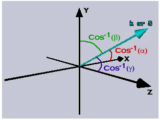
The direction of propagation is the unit vector in the k direction k/|k| = aax + bay + gaz Then, k = (2pn/l)(aax + bay + gaz) The position vector r = xax + yay + zaz so that k•r= (2pn/l)(ax + by + gz)]
The constants a, b, and g are direction cosines for the x, y, and z axes, respectively. The direction cosine is the cosine of the angle between the k vector and the coordinate axis. For example, a z-propagating wave has a = 0, b = 0, and g = 1. It has angles of p/2 radians between k and the x and y axes and an angle of 0 radians with the z axis.
|
The power flow for an optical plane wave is generally described by the time-averaged Poynting vector due to the high frequency in the optical spectrum.
Time-Averaged Poynting Vector (W/m2): S = (1/period) òperiod Sinstananeous dt = (1/2) |E| |H| ae ´ ah S = (1/2) (|E|2 / h) k/|k| = (1/2) (|A|2 / h) k/|k| S = (1/2) E´ H*
Time-Averaged Irradiance (W/m2): I = |S| = (1/2) |E| |H| = (|E|2 / 2h).
Optical Path Length: The optical path length between two points in some media or set of media is the distance in a vacuum that would produce the same phase change. Mathematically, the optical path length is index of refraction times the propagation distance. Consider a +z-propagating plane wave at time t = 0.
The electric field in a vacuum (n=1) varies with z only (at this snapshot in time) and is E (z, 0) ae = |E| cos[+(2p/l)z + Q] ae The phase of the wave changes by a full cycle (2p radians) for every Dz = l.
The electric field in a dielectric with n varies with z only (at this snapshot in time) and is E (z, 0) ae = |E| cos[+(2pn/l)z + Q] ae The phase of the wave changes by a full cycle (2p radians) for every nDz = l. The optical path length between z = z1 and z = z2 is n(z2 – z1).
For a set of dielectric layers perpendicular to the propagation direction, the total optical path length is SnmDzm = n1Dz1 + n2Dz2 + ….. where nm and Dzm are the index and thickness of the mth layer.
A media in which a plane wave is propagating may be lossy. The field amplitudes decrease at a rate proportional to the field magnitude. The resulting loss may be represented by an attenuation constant aL in units of Nepers per meter (Np/m). (The symbol aL is a different quantity than the direction cosine with respect to the x axis a.) The attenuation constant is positive for a lossy media, zero for a lossless media, and negative for a media with gain. Consider the loss for a plane wave in a homogeneous media.
The defining differential equation for the complex amplitude (A = |E| exp(+jQ)) of the phasor electric field is [(¶/¶x) + (¶/¶y) + (¶/¶z)] A = - aLA. The solution is A = Ao exp[- aL(aax + bay + gaz)•r] = Ao exp[- aL(ax + by + gz)] Where Ao is the value of A at the position (0,0,0).
The field quantities become E (r, t) ae = |Ao| exp[- aL(ax + by + gz)] cos(- wt +k•r + Q) ae H (r, t) ae = (|Ao|/h) exp[- aL(ax + by + gz)] cos(- wt +k•r + Q) ae
The resulting Poynting vector is S = (1/2) E´ H* = Io exp[- 2aL(ax + by + gz)] k/|k|. where Io = (1/2) (|Ao |2 / h). |
For example, a +z-propagating plane wave in a lossy material has the following electric field and Poynting vector. E (z, t) ae = |Ao| exp[- aLz] cos(- wt + kz + Q) ae S = (1/2) E´ H* = Io exp[- 2aLz] az .
This loss does not include reflection loss at interfaces.
Care must be taken to distinguish between the exponential loss constant for fields and that for irradiance. The attenuation constant aL as defined here refers to fields. The corresponding exponential loss constant for irradiance is 2aL. Some texts, especially in the semiconductor field, will define the latter quantity (2aL) as an absorption coefficient with units of inverse meters (m-1) or inverse centimeters (cm-1). Note that the terminology and symbol notation are sometimes used interchangeably in the literature.
|

